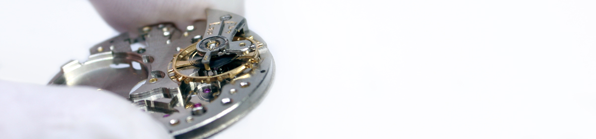

This post pertains to a Valjoux 23 chronograph movement which was received in the same freezer bag from China as the Universal Genève Uni-Compax I recently serviced. The bag contained multiple chronograph movements which were all in bad shape. I actually received two Valjoux 23 movements, but this one had a working balance and Incabloc shock protection thus making it the better candidate for restoration.
Little did I know that this movement had been terribly violated by the previous owner(s). The problems I encountered are almost too numerous to list, but I’ll do my best to recount each horror unveiled during the recovery process; yes, this service is probably better described as a recovery in lieu of a repair.

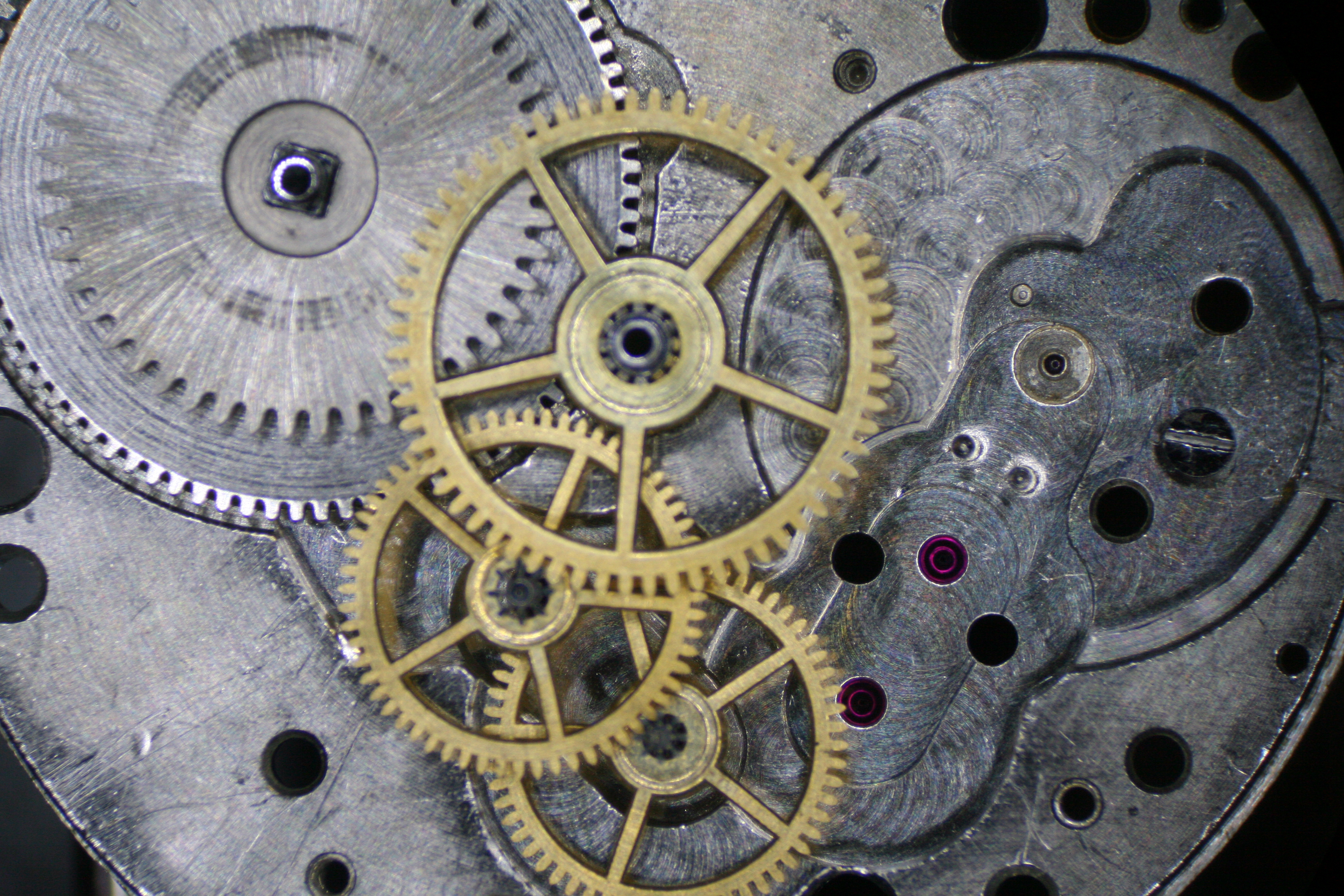
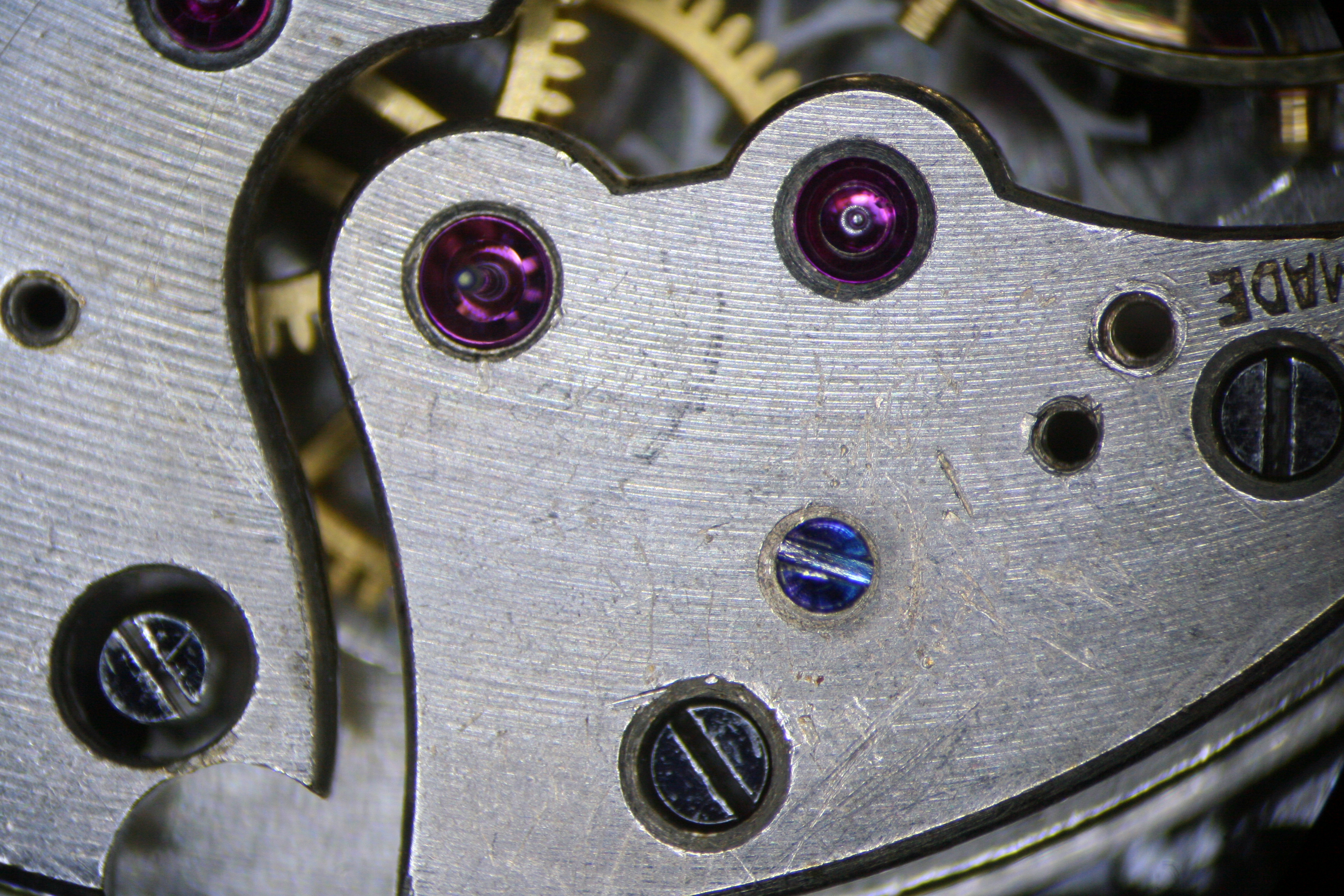
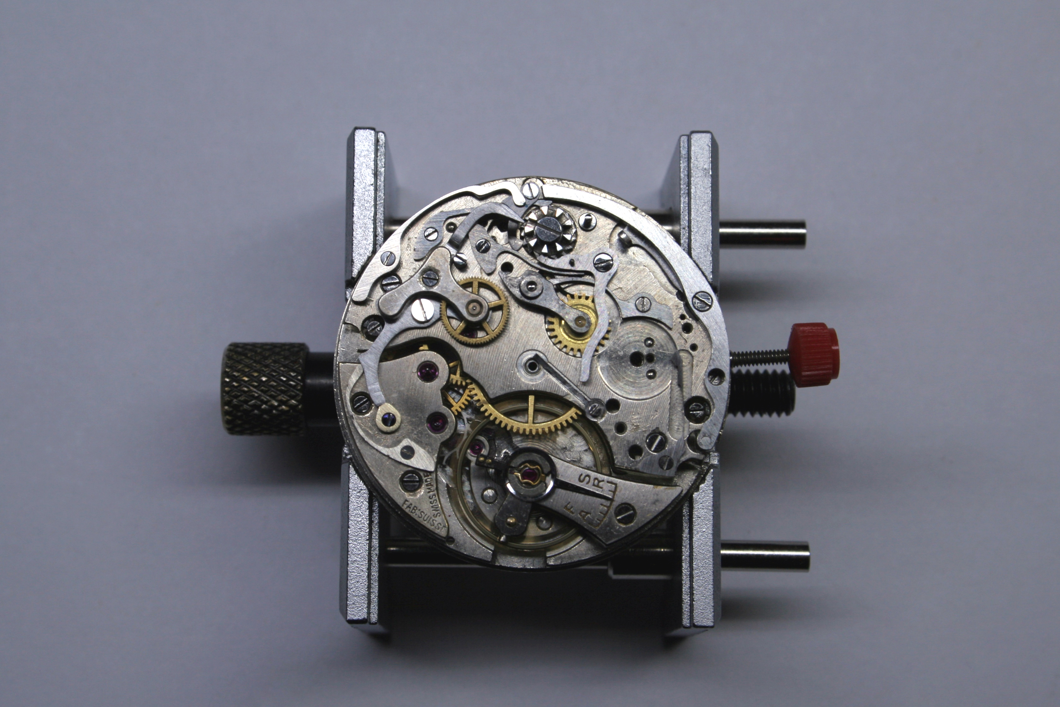
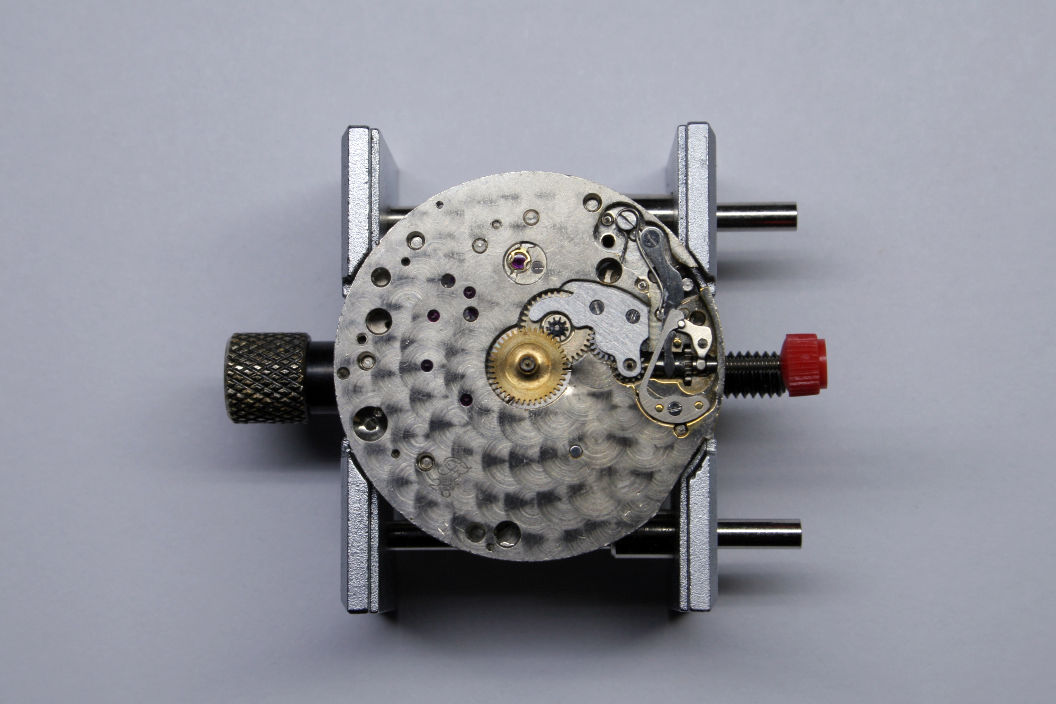
Initially things didn’t look too bad (I apologize for not having images of the movement in it’s original state) as the movement was probably 90% complete and is a nicely decorated. The Main Plate has a beautiful perlage finish both on the dial side and beneath the Balance Wheel and the Balance Wheel sports the concave arms and extra screws usually found in high end Valjoux movements.
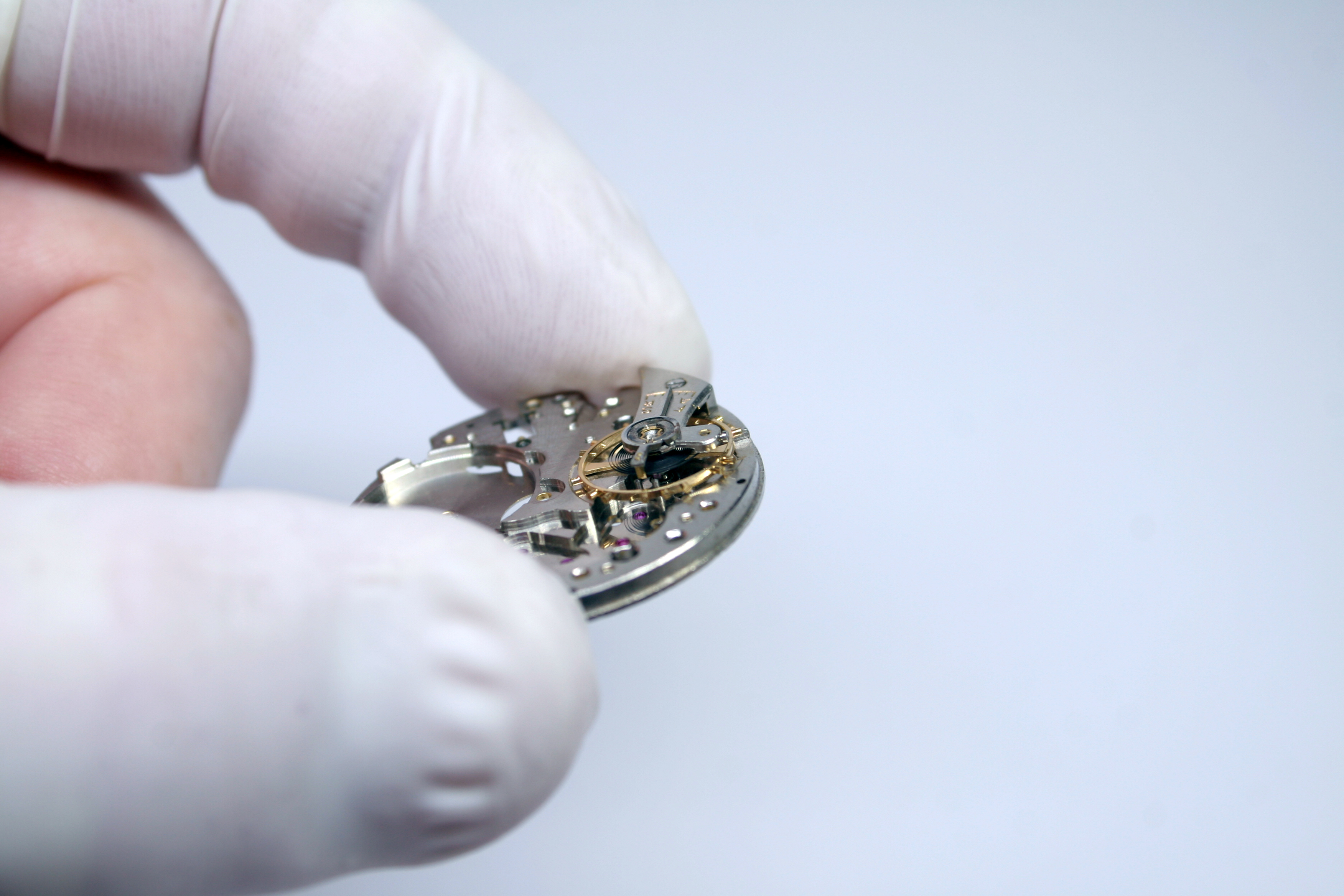
Sadly, the movement was filthy so I immediately commenced breaking it down for cleaning.
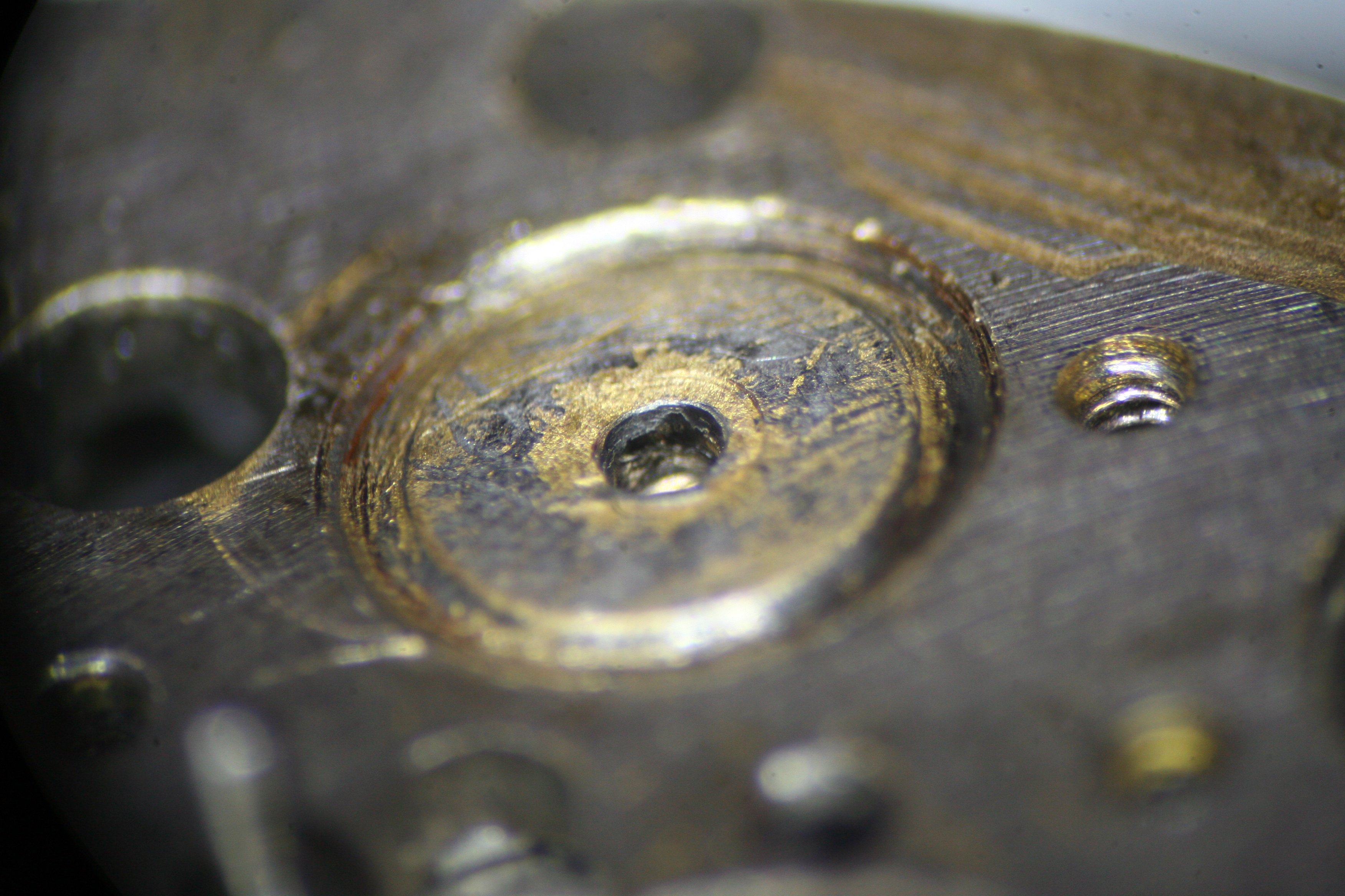
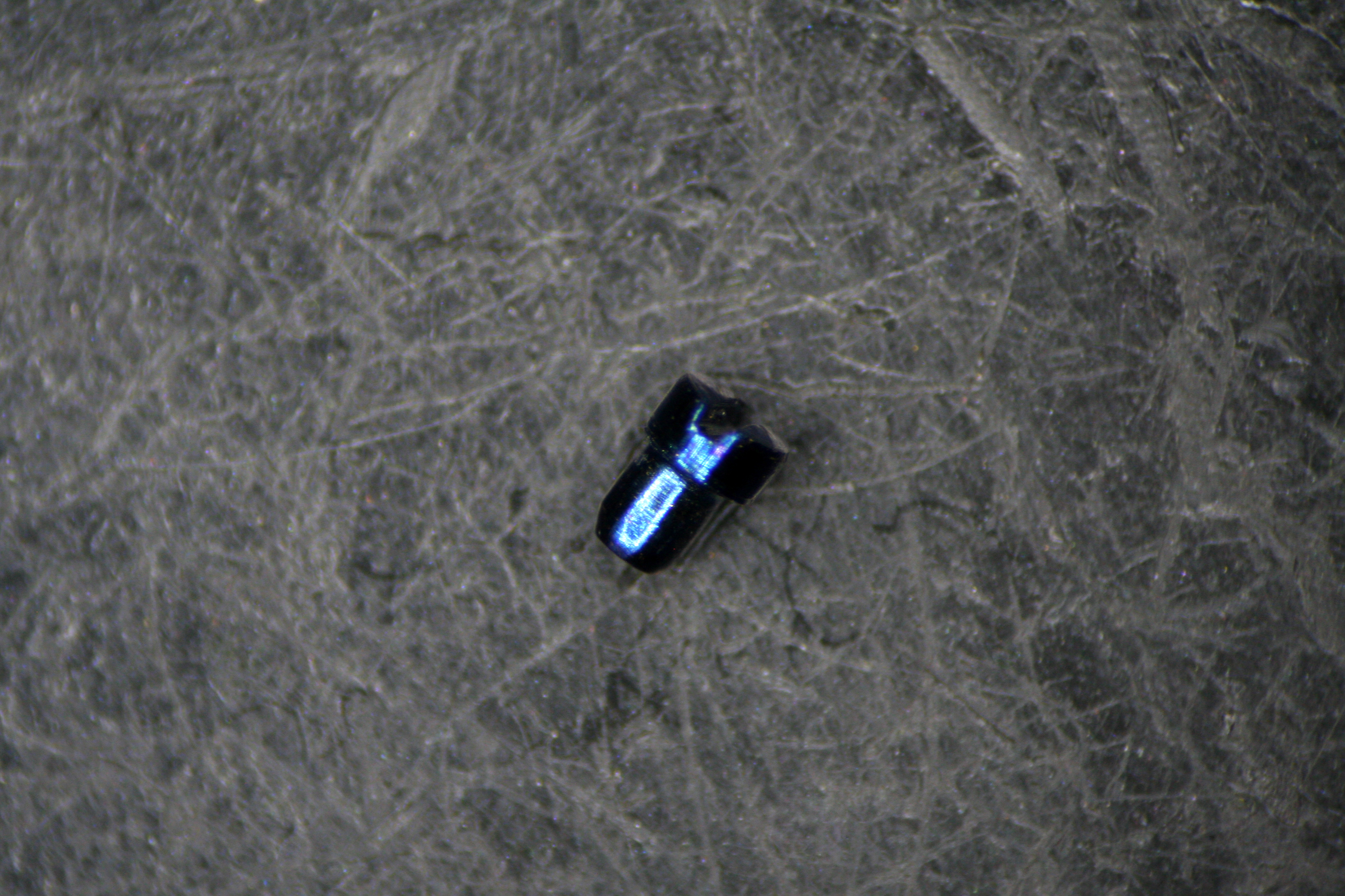
The first problem I encountered was with the Pillar Wheel. The screw securing the wheel to the Barrel Bridge refused to come out. I assumed the threads were stripped until I had finally succeeded in removing the screw from the bridge, which I only did by pushing it out with the staking kit. The “screw” turned out to not be a screw at all but instead a custom fabricated rivet. I’m still confused how anyone would think it was a good idea to replace a watch screw with a rivet. Now I had a damaged Barrel Bridge and a useless rivet.

Naturally this meant I would need to either (A) re-tap the formerly threaded hole and custom fabricate a screw to fit the new thread or (B) drill out the hole, press in a bushing, and tap the bush to fit the correct screw. I settled on option B.
Next I spied some steel broken off in the Barrel Bridge. The screw for the Operating Lever Spring had been sheared off. Then I noticed that the screw for the Coupling Clutch Spring was also broken off in the Train Bridge. This kind of vandalism gets my blood boiling. Fortunately, both screws had snapped off in brass plates so I was able to use a simple alum bath to dissolve the steel instead of drilling out the broken shafts.
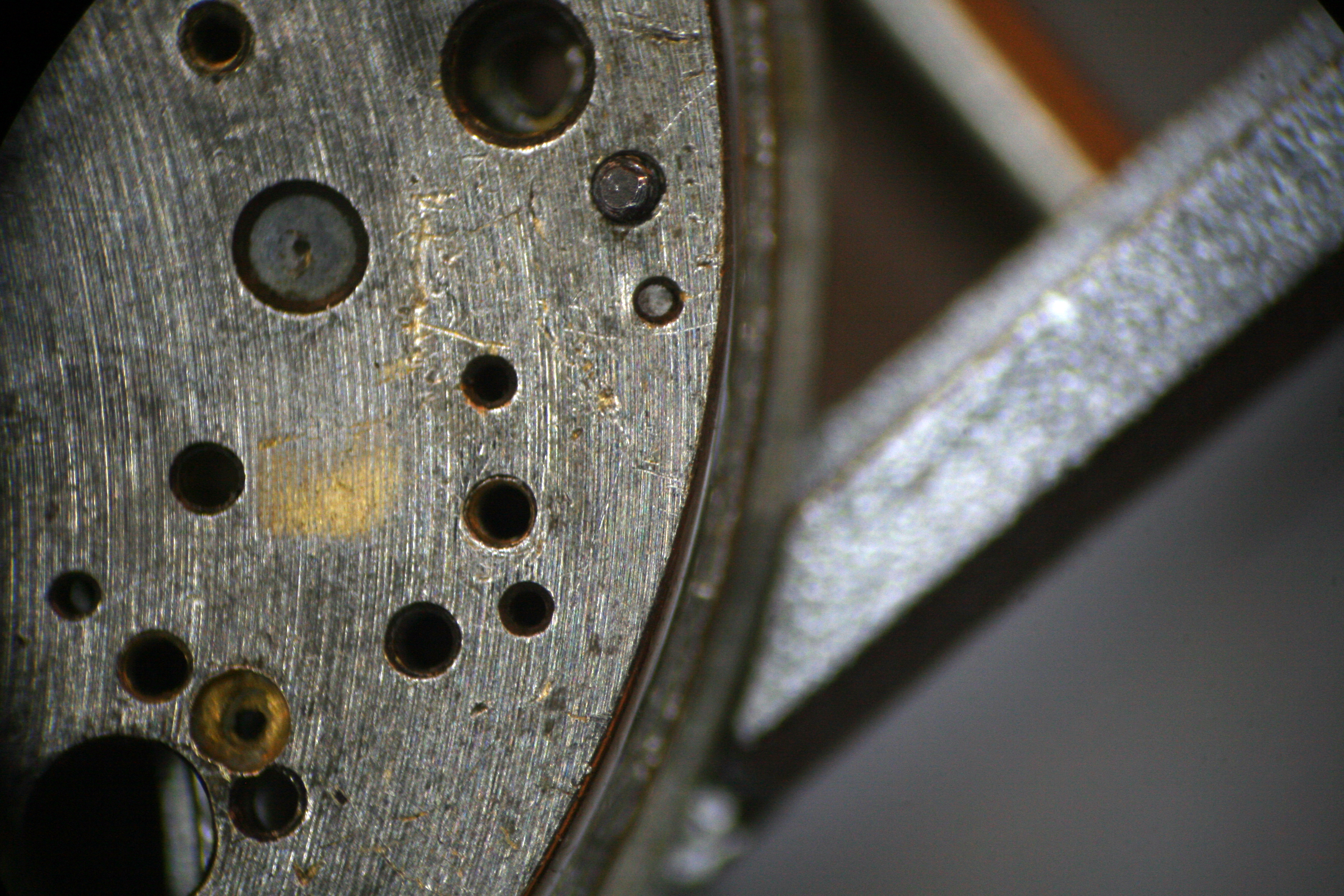
With the Barrel Bridge off and the gear train out some new issues came to light. First, the Mainspring Barrel and Barrel Arbor were missing; both would need to be replaced in order to get this piece running. Second, the pilot bearing for the Stem was worn out. The pilot bearing supports the far end of the Stem (the other end being screwed into the Crown); when it’s heavily worn the Stem has too much lateral movement resulting in slippage of the Winding Pinion.
The bearing is pressed into the Main Plate; to remove the played out bearing, a tap was threaded into the pilot hole and the bearing pulled free with the aid of a pin vise. A replacement was then turned on the lathe and pressed in with a stake. A dollop of solder was applied to guarantee a permanent fit.

Having covered all of the mechanical gremlins I could see, I now had time to frown upon the cosmetic issues. Deep scratches were in abundance but more unsettling was the solder or lead which had been splashed on the Barrel Bridge and Coupling Clutch.

Using a hot iron and a solder wick I was able to remove lead from the Coupling Clutch. Sadly, I was not as successful removing the lead from the Barrel Bridge but it lies on the underside and is strictly a cosmetic nuisance.
I had now reached the point where I could run the movement through the watch cleaner. A few runs through the ultrasonic bath was followed by a thorough cleaning in the old L&R machine. A bit of elbow grease and Rodico chipped in too.
Soon a replacement Mainspring Barrel and Arbor arrived from Scotch Watch along with a new Mainspring from Jules Borel.

With these parts in hand I could commence with assembly, which went smoothly…

At least until I got to the Train Wheel Bridge where I discovered the jewel for the Fourth Wheel was chipped. (sigh)
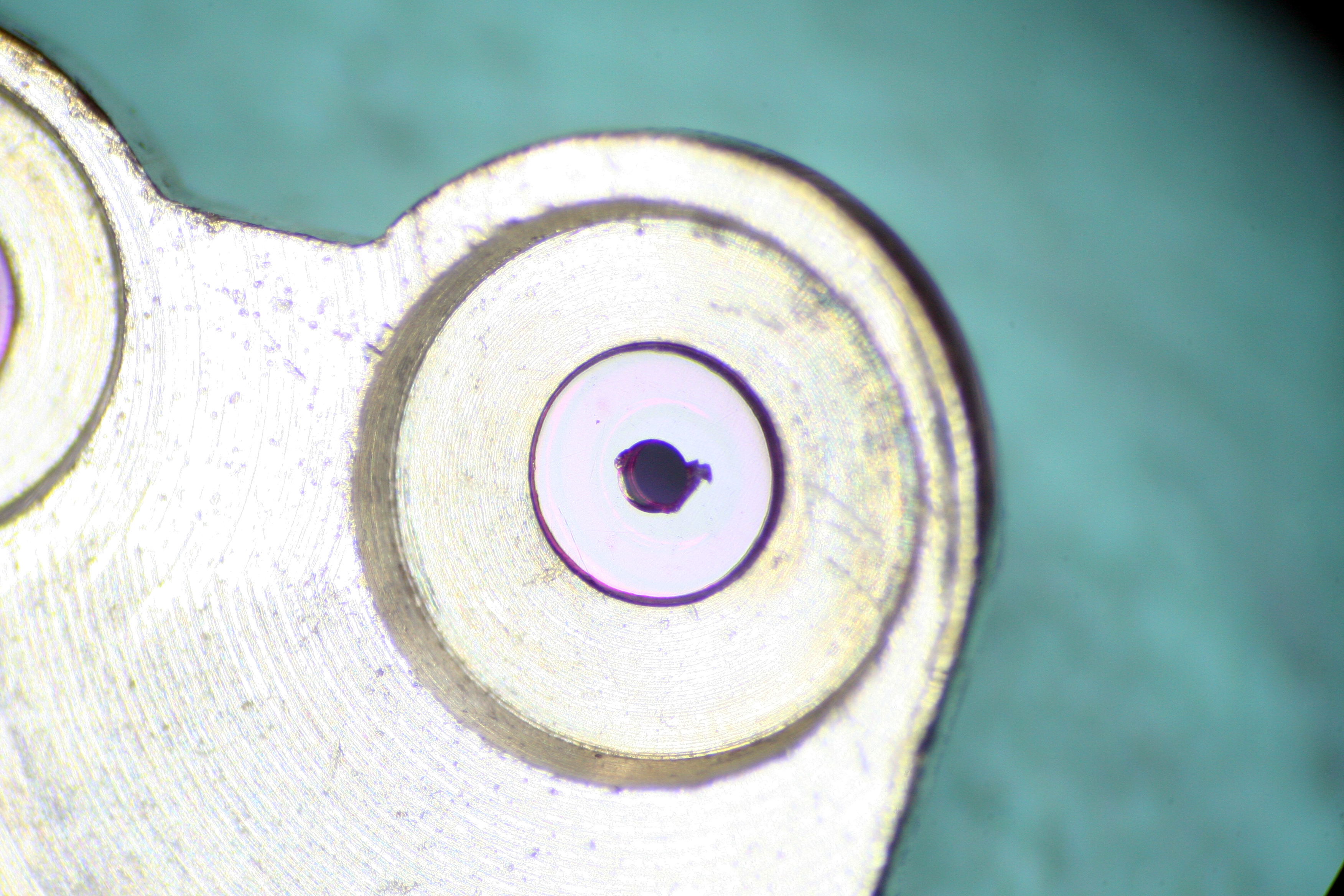
Normally replacement jewels are not too difficult to get ahold of, but in this case the proper sized jewel was no longer available. The closest I could find was a jewel that had an outside diameter 0.2mm wider than the original. Cousins had it in stock but the price was high. No matter, jewels come in sets of three so I’d have two spares for the next Valjoux movement- or so I thought! Turns out this jewel was only sold as a single! Blast! It may not be the largest, but it is the most expensive jewel I’ve bought to date.
I fit the replacement jewel and completed assembly of the base movement. A bit of lubrication and a good wind netted fair results on the timegrapher.

Now it was time to assemble the chronograph layer and this naturally did not go off without a hitch.
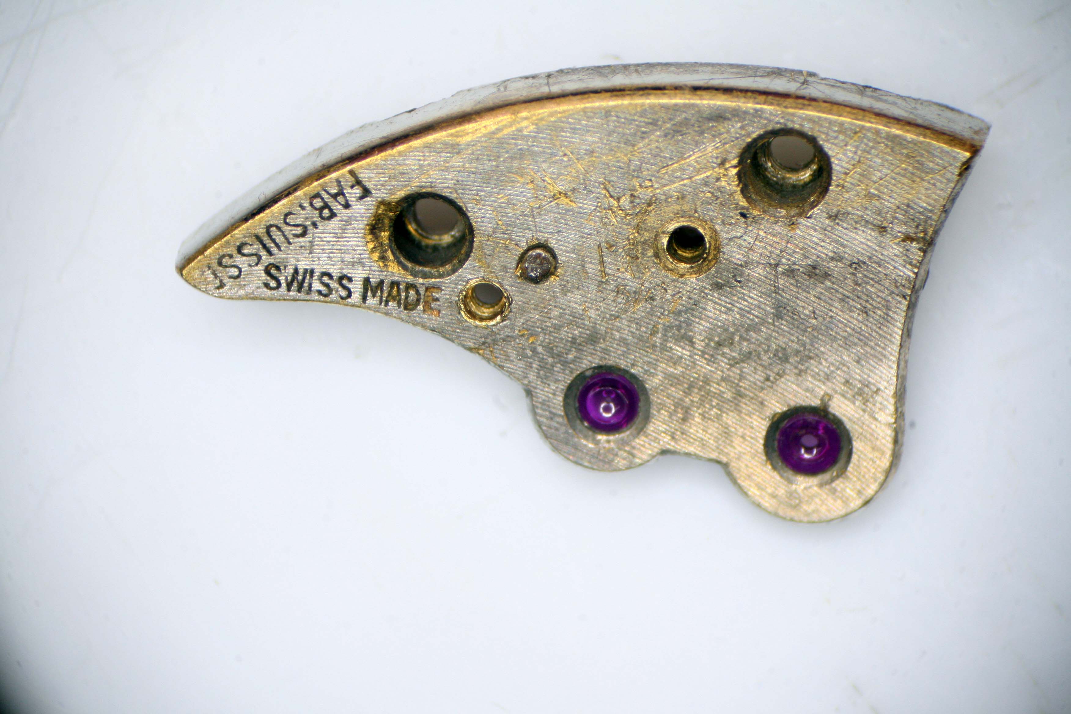
I moved step-by-step through Esembl-O-Graf: Volume 4 and almost immediately encountered a problem with the Blocking Lever Spring. The Blocking Lever holds the Chronograph Runner when the chronograph mechanism is stopped. This keeps the Sweep Second Hand from drifting. The Blocking Lever Spring places tension on the Blocking Lever, without this the lever cannot do it’s job.

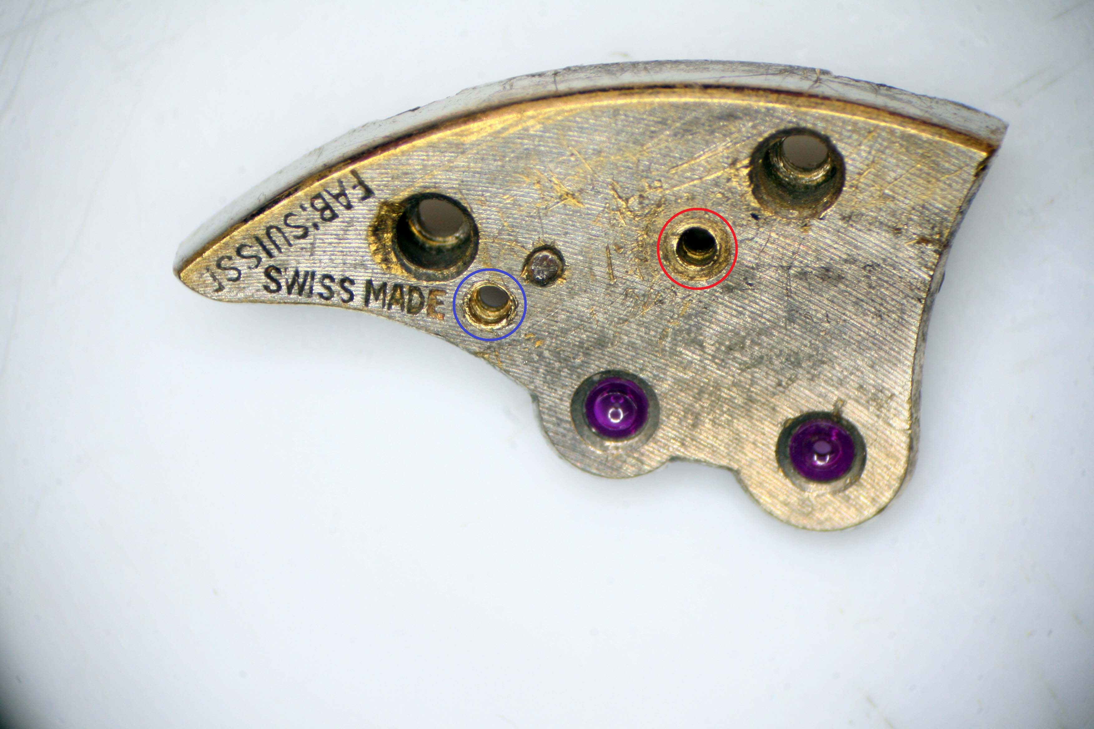
Unfortunately for me someone had reamed out one of the two pilot holes used to position the Blocking Lever Spring and as a result the spring couldn’t hold any tension on the Blocking Lever.
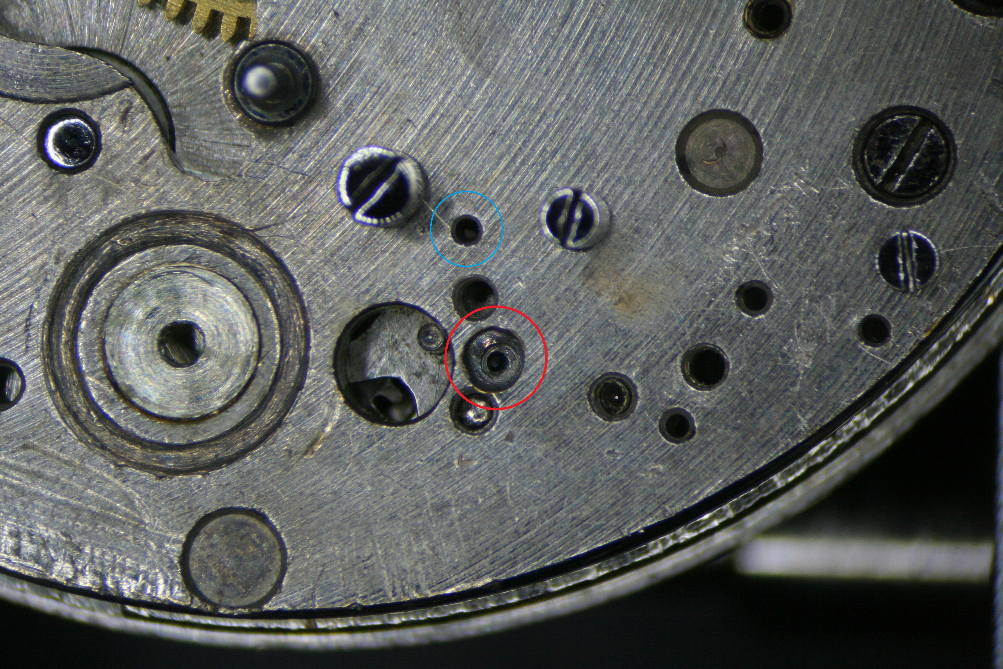
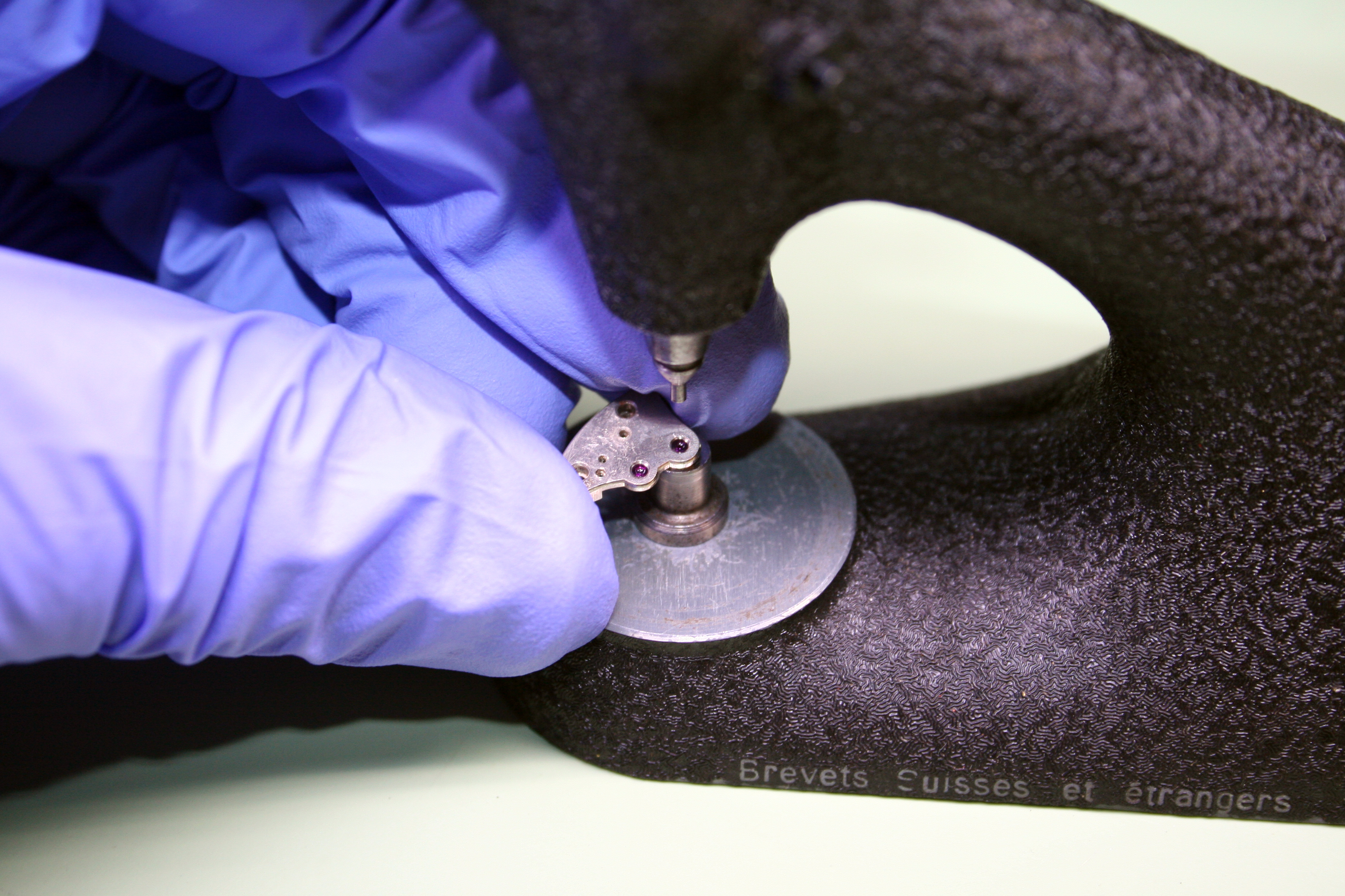
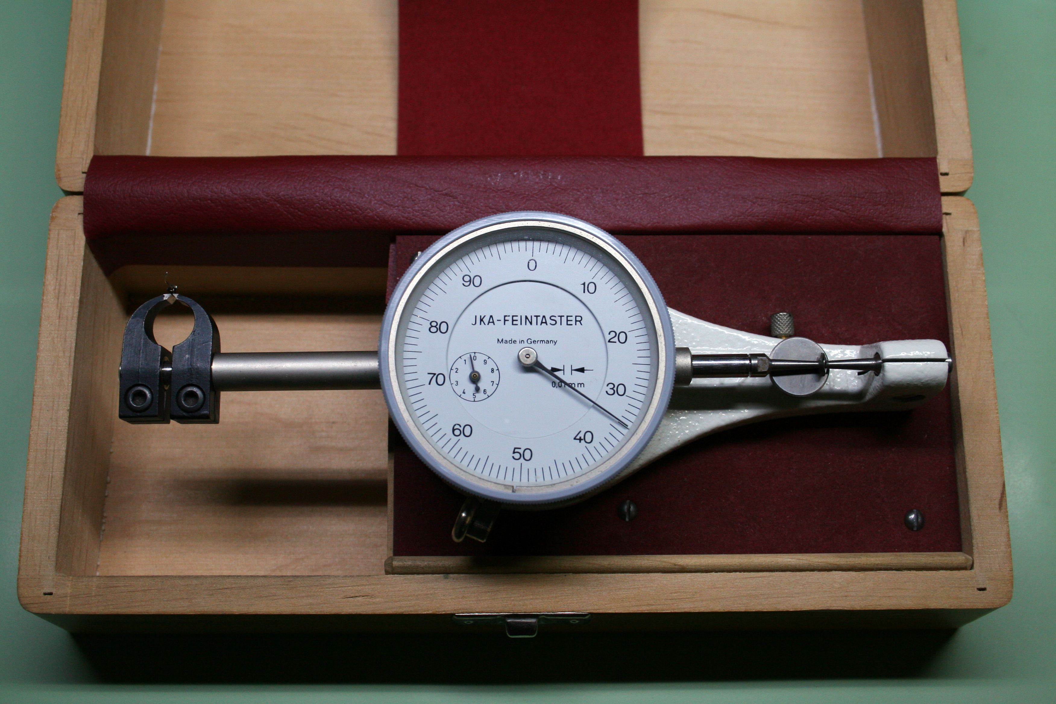
To correct this, I again employed my Seitz jeweling tool. The tool allows a technician (me) to place a concentric hole in the bridge, the diameter being measurable down to a hundredth of a millimeter. This hole was then filled with a brass slug into which a new pilot hole was bored. The pilot hole for the Blocking Lever Spring is quite small. To set the size, I measured the diameter of the guide pin on the micrometer- just 0.34mm!
With that fix out of the way I gained a bit of momentum. The rest of the chronograph layer came together without incident except for the eccentric for the Sliding Gear which simply wouldn’t fit snugly in its hole. I had to remove the eccentric when the Barrel Bridge was soaked in the alum bath way back when. I didn’t want to lose the eccentrics too so I pulled them from the bridge only to discover this one wasn’t a snug fit anymore. Bother.
I ignored this problem and plowed on; the movement slowly taking shape until… (wait for it) A new problem!
This time the the issue I had was with the Coupling Clutch. The Coupling Clutch allows power to be transmitted from the Chronograph Driving Wheel to the Chronograph Runner. The Chronograph Driving Wheel is fitted atop the extended pivot of the Fourth Wheel. When the clutch is engaged, the clutch wheel (which is in constant contact with the driving wheel and therefore always in motion) is brought in contact with the Chronograph Runner; in this way power is transmitted to the Sweep Second Hand, placing it in motion.
The Coupling Clutch is mounted on an adjustable eccentric. Turning the eccentric allows you to make fine adjustments to the clutch- this is important to control how much friction and pressure is generated when the clutch is engaged- too much and the watch will stop, too little and no power will be transmitted to the Chronograph Runner.
The someone must not have appreciated this as they removed the eccentric and replaced it with a (non-adjustable) screw. This “fix” required a modification to the clutch as well- the hole for the eccentric was drilled out and replaced with a bushing. A file was taken to the bottom of the clutch lever to accommodate the bushing.

This put me between a rock and a hard place. A proper NOS eccentric would no longer fit in the Train Wheel Bridge since the hole had been drilled out and tapped. Nor would the eccentric fit the clutch since it too had been modified. The proper fix would be to repair the hole in the bridge, and order a replacement clutch and eccentric and at this point, pouring more money into the service seemed unpalatable.
In fact the situation was even worse than that. I soon noticed that the pilot hole for the Coupling Clutch Spring had been drilled out as well (good lord, what was wrong with this fellow?). So the proper fix would be to repair both holes in the bridge and replace the Coupling Clutch and eccentric.
Having already exceeded my budget for this project, I opted for an in-house solution. First, I returned the Coupling Clutch to spec by riveting a brass bushing to the damaged hole. This bushing was then carefully filed down to the original dimensions of the clutch arm and the hole for the eccentric carefully broached to the proper dimensions (0.95mm diameter).
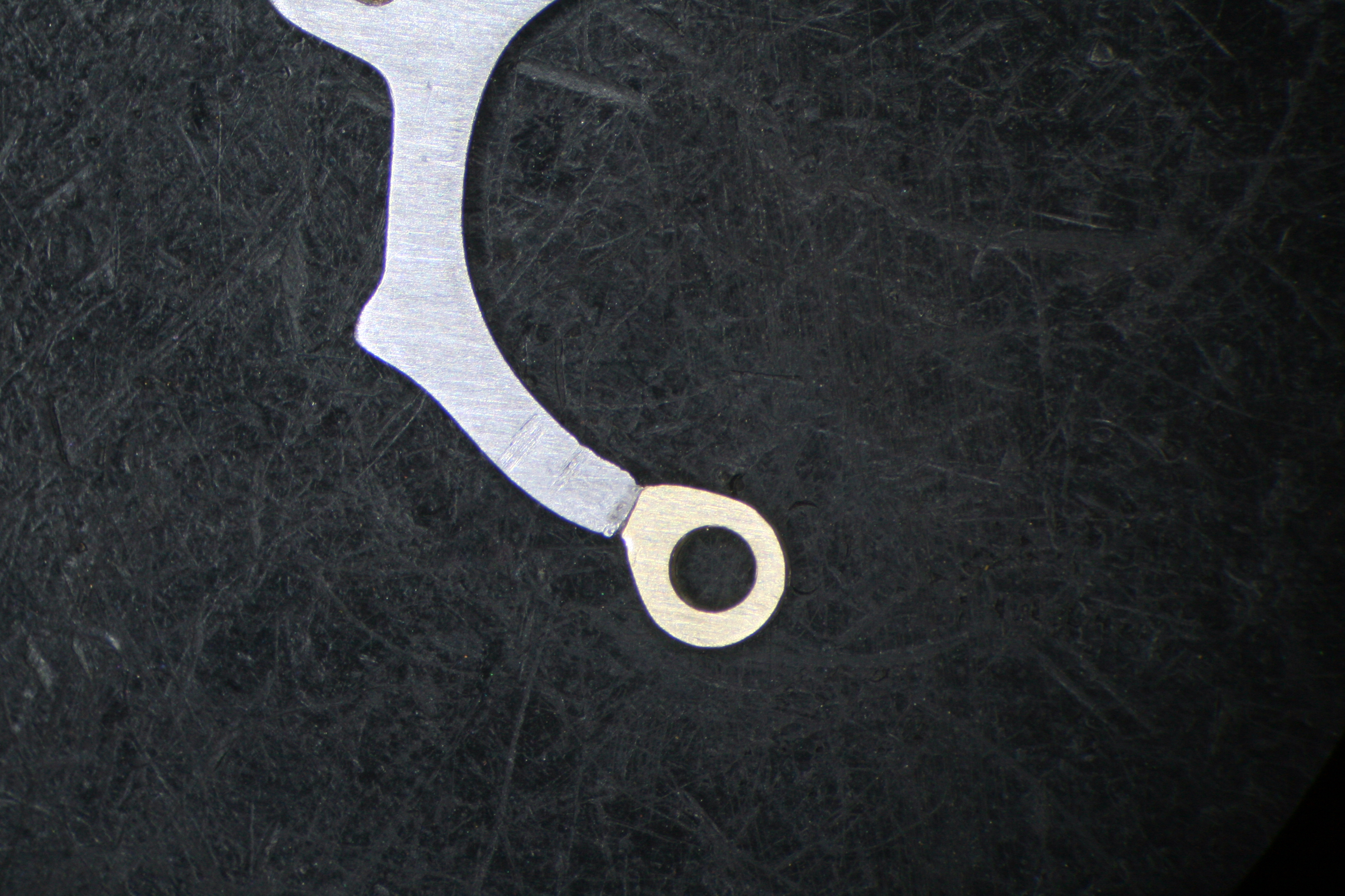
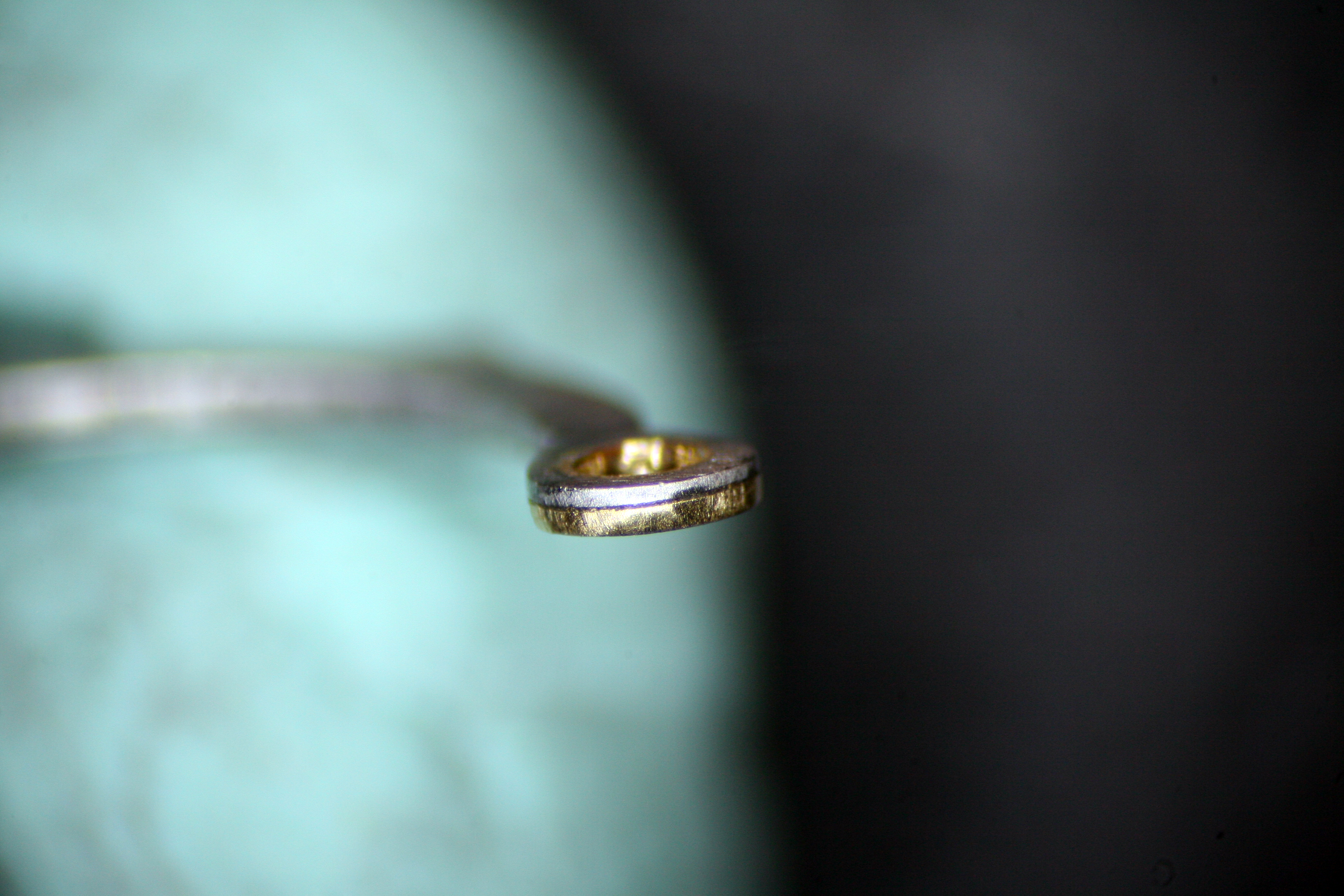
With the clutch arm repaired, I was on to fabricating an eccentric. Now, I’ve never turned an eccentric on the lathe before and a bit of research suggested the tool needed for the job (a four jawed chuck) was not in my kit.
To clarify, an eccentric appears to be a screw on the surface, but the shaft beneath the head is off center and is not threaded. This results in the eccentric turning around the perimeter of hole it is fixed in as opposed to pivoting directly from the center of the hole. Since the shaft and the head do not share a common center point, turning an eccentric on a lathe is not as simple as turning a screw.
My solution to this problem was to turn the eccentric head on the lathe as I would any other screw, then use fine escapement files to finish the off center shaft. The result is something that looks a bit home-made but works just as desired.
I still had at least one more problem to fix though- the pilot hole for the Coupling Clutch Spring… but since this project was getting a bit long in the tooth, I decided to save that for another day. After mounting the clutch I secured the spring and noted that it struggled to keep tension on the clutch as I had expected. There’s no way around it, I’ll need to revisit this later.
Thankfully, there were no more gremlins to uncover and I was able to complete assembly of the movement. A test of the chronograph confirmed proper functionality although fixes to the clutch spring and Sliding Gear eccentric will need to be implemented to guarantee consistent proper operation.
Despite this, I’ve finally reached a point where I can enjoy the fruits of my labor. I don’t have a case for this movement but just seeing it ticking on the bench is rewarding. This movement was dead but not anymore. It is also quite a fine movement- the Valjoux 23 and 72 chronograph movements were considered by many the best of their era (although Longines and Lemania fans may dispute this). This particular piece had quite a fine finish, although it does have many, many scratches now.

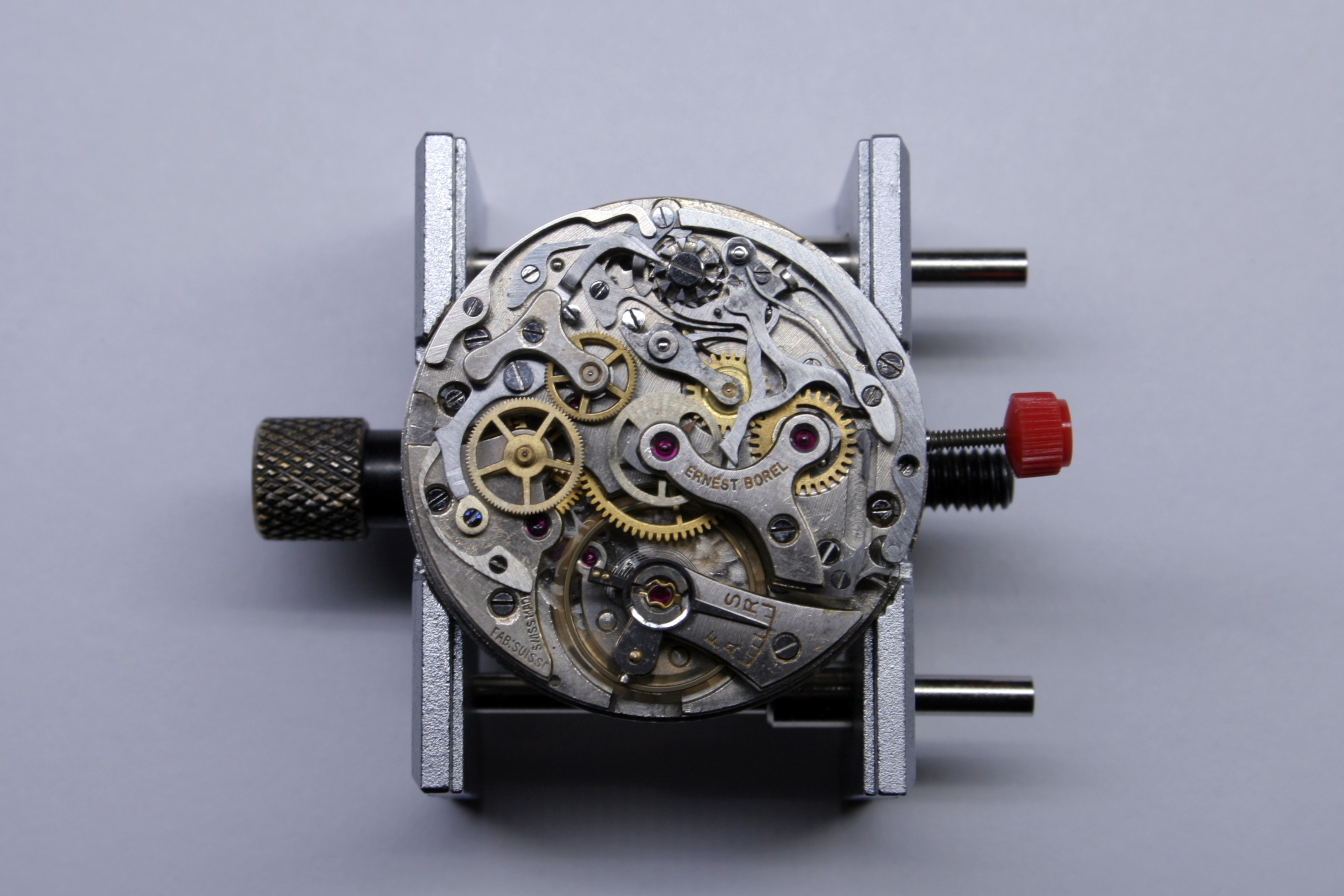
With no watch case to place this movement into I’ll probably end up breaking it back down and selling it for parts (although the thought occurred to me that I could mount it in acrylic and use it as a fine paperweight). The Valjoux 23 movement shared many parts with the highly coveted Valjoux 72– a movement that can be found in prestigious watches such as the Rolex Daytona. Valjoux ceased production of the 23 (and 72) movement in the early 1970’s when they focused instead on the 7733 and 7750 family of movements. Today parts supplies are dwindling making a orphaned movement like this a good candidate as a donor.

Beautiful!
That was a good read!
Congrats on your skills! I believe they are improving!
That was a Lazarus movement – and you brought it back from the dead 🙂
LikeLiked by 1 person